Almost every electronic sensor that "sees" something — a presence detector in a smart building, a barcode scanner on a parcel, a robot vacuum dodging a chair leg, the IR receiver behind your TV's screen, or a photoelectric sensor watching parts on a conveyor — depends on light. And for the vast majority, it is a kind of light most of us never see. Understanding modern optical sensing begins not with the housing or the microcontroller, but with the spectrum itself, and a small family of components that bring a useful slice of that spectrum onto a circuit board.
How does the light spectrum break down?
Light is electromagnetic radiation, classified by its wavelength — the distance between successive peaks of the wave, measured in nanometres (nm, billionths of a metre). The full spectrum runs from gamma rays at the shortest end to radio waves at the longest. The slice that matters for optical sensing sits in three adjacent bands.
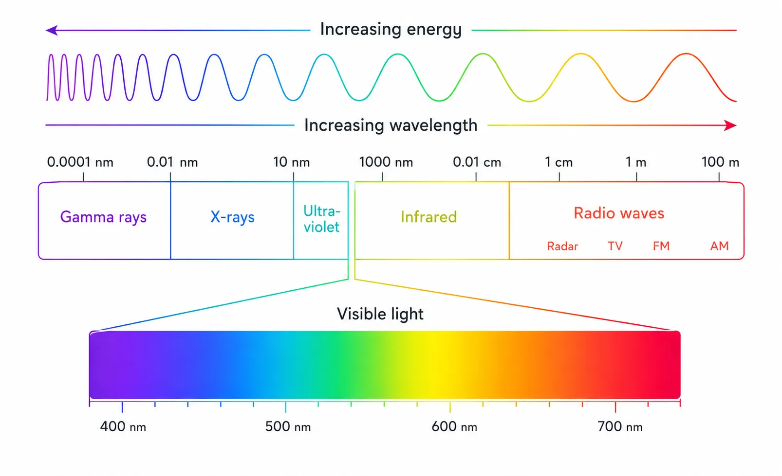
- Ultraviolet (UV), roughly 10 to 400 nm. Shorter wavelength, higher-energy photons. UV is used to sterilise drinking water, cure adhesives, authenticate banknotes, and in sensing applications to drive fluorescence detection on pharmaceutical and packaging lines, where certain inks and labels emit visible light when illuminated with UV.
- Visible light, roughly 380 to 780 nm. The narrow band the human eye evolved to use, from violet through green to deep red. It powers indicator LEDs, displays, and any sensor whose beam an installer needs to see for alignment. Bright visible red around 660 nm is the workhorse here.
- Infrared (IR), beyond 780 nm. Invisible to humans. Every object warmer than absolute zero radiates some IR, which is why thermal cameras can "see" people in the dark. For optical sensing, what matters is that IR can be produced cheaply with semiconductors and detected cheaply with silicon, without disturbing the people nearby.
Why infrared?
The infrared band was discovered in 1800 by Sir William Herschel, an astronomer better known for discovering Uranus. While studying sunlight through a glass prism, Herschel placed a thermometer in each colour band and noticed that the temperature kept rising as he moved past the red end into a region that appeared to be empty. The thermometer in that empty zone climbed higher than any of the visible bands. Herschel had detected light he could not see. He called it "calorific rays"; the term infrared, Latin for "below red," came later.
Two centuries on, the band Herschel stumbled onto powers a quiet majority of modern optical electronics. The reason is simple: silicon photodiodes — the cheap, mass-produced detectors at the heart of every camera and most sensors — peak in sensitivity around 850 to 950 nm. Two specific wavelengths dominate today's industrial designs: 850 nm, slightly cheaper to manufacture, and 940 nm, fully invisible and benefiting from a small dip in the solar spectrum that improves rejection of ambient sunlight.
Where do IR LEDs show up?
Photoelectric sensors in industrial automation
|
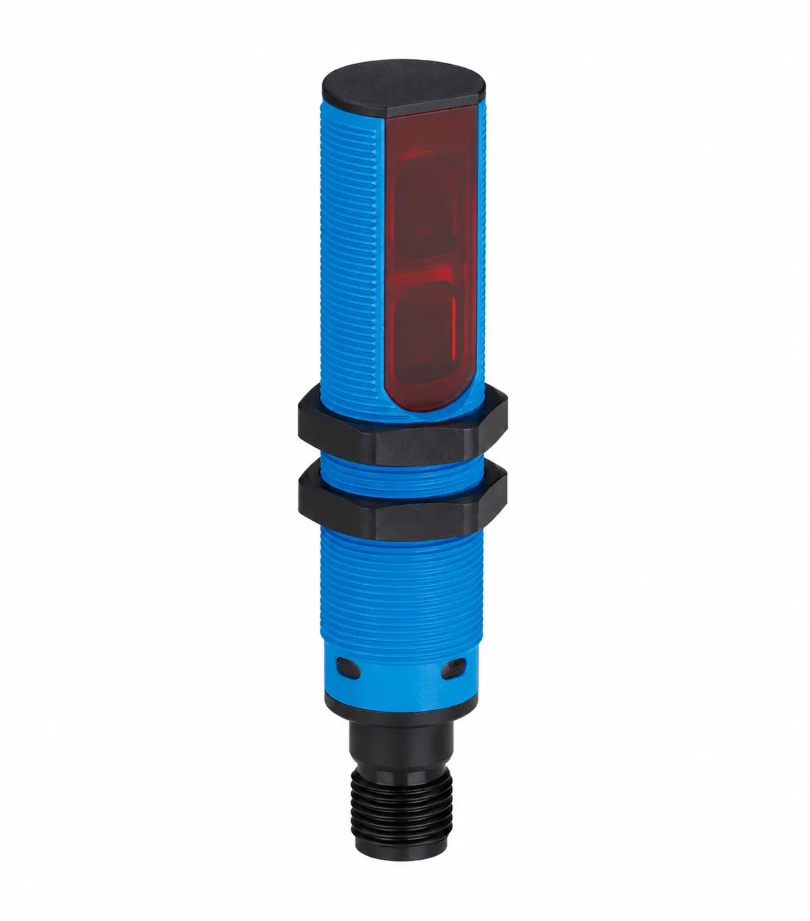
The single largest market for industrial IR LEDs is the photoelectric sensor: small cylindrical devices, typically with M12 connectors, that watch every conveyor and robot cell on a modern factory floor. They detect parts, count cycles, verify presence, and trigger actions. Most operate at 940 nm, in one of three classical optical topologies: through-beam, retroreflective, or diffuse. |
Light curtains and object detection
|
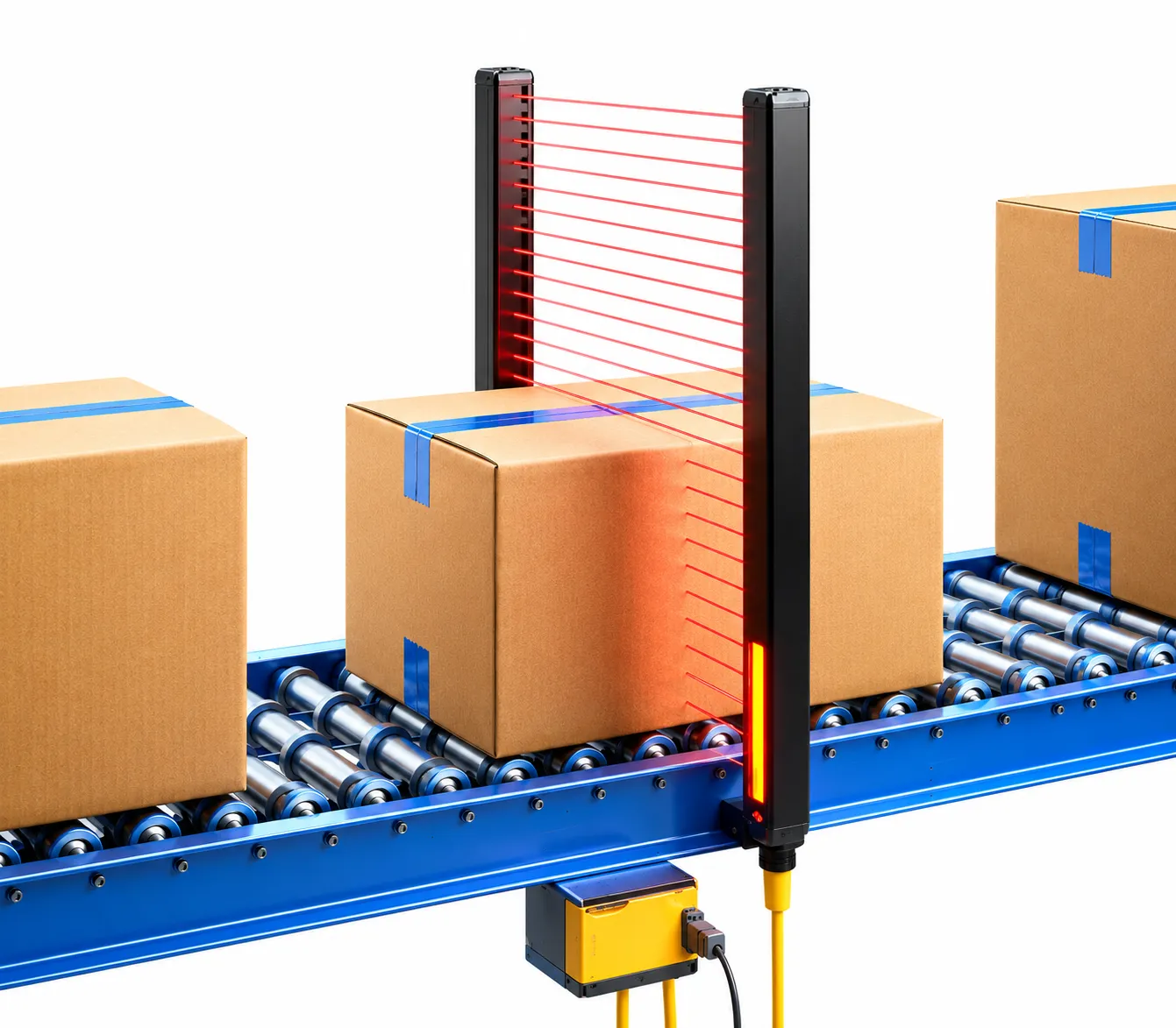
A light curtain is a vertical array of paired IR emitter–receiver beams stacked one above another. As an object travels through the curtain — for instance a box moving along a conveyor — the array continuously reports which beams are blocked and which remain clear, giving the controller a real-time silhouette of the object's height, position, and leading edge. These systems rely on narrow-angle, high-intensity emitters paired with closely matched narrow-angle receivers, fired in a fast modulated sequence so adjacent beams don't interfere with each other and ambient light is rejected. |
Remote control and IR data links
|
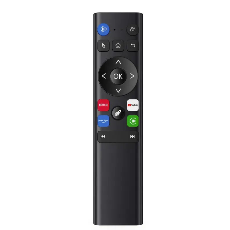
The IR LED at the end of every TV remote control transmits a 38 kHz modulated digital pulse train at 940 nm; a matched photodiode behind the TV's IR window receives it. |
Emitter and receiver: the basic pair
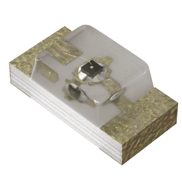
Every optical sensor in the categories above reduces to two semiconductors having a conversation in light.
- The emitter is an IR LED. Push current through it the right way and it emits invisible IR, typically at 850 nm or 940 nm. The light goes out into the world, reflects, scatters, or fails to come back at all.
-
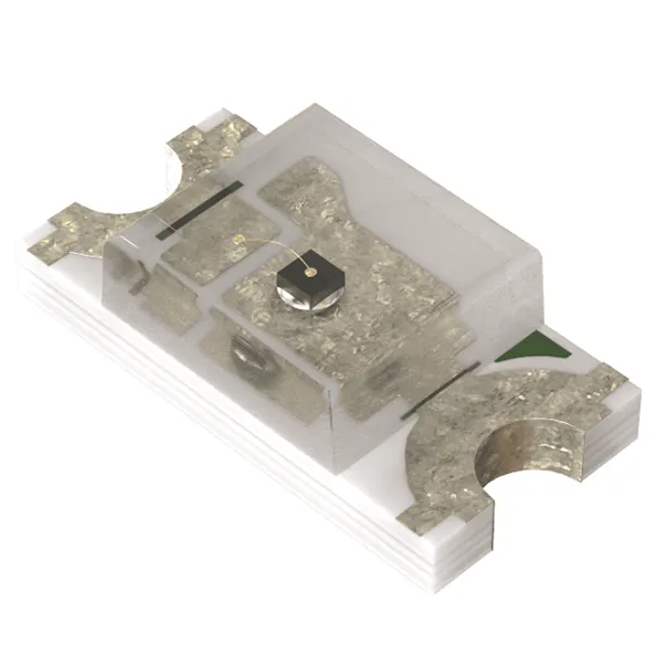
The receiver, sometimes called photodetector, is the reverse: a semiconductor that converts incoming IR back into an electrical signal. It comes in two options.
- A photodiode (PD) generates a small current, typically microamps, proportional to the IR light striking it. Its great virtue is speed: it responds in nanoseconds and it is suitable for ToF (Time-of-Flight) applications. The trade-off is that microamp signals normally need an external operational amplifier on the PCB.
- A phototransistor (PT) is the same idea with a built-in amplifier stage. Output is much larger — milliamps instead of microamps. The trade-off is response speed: PTs work in microseconds, fine for switch-style detection but not for ToF or fast modulated systems.
Inside the Edison CHIP IR LED portfolio
Every CHIP LED design therefore begins with two choices: which wavelength to transmit, and which kind of receiver to pair with it.
Edison Opto's CHIP LED selection guide organises every IR part along five axes: type (emitter or receiver), package size, direction, wavelength, and viewing angle. Reading those five columns is the same as specifying a part for a sensor design.
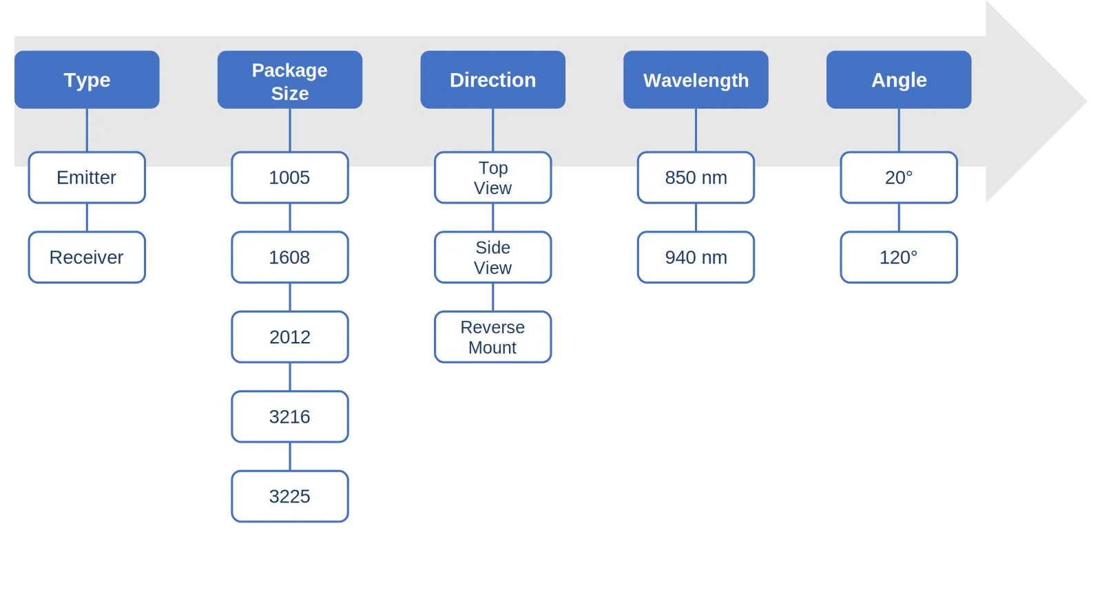
- Package size: Larger packages dissipate heat better, tolerate higher drive currents, and produce more optical output but at the cost of board area. For most industrial sensor PCBs, the 3216 has become the de facto choice — large enough to handle currents typical of photoelectric work, small enough to fit inside an M12 sensor housing.
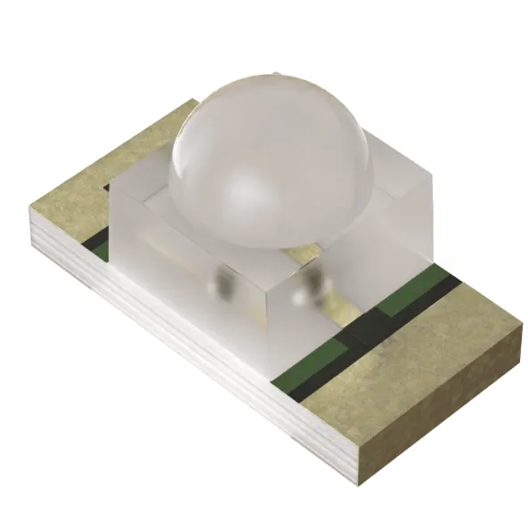
- Direction: The same chip can be packaged so its emitting surface faces three different ways. Top View emits perpendicular to the board (the default). Side View rotates the LED 90° so light exits parallel to the board surface, useful in slim modules where the optical path runs along the PCB's edge. Reverse Mount packages the LED upside-down through a cut-out in the PCB, emitting down through the board, for ultra-compact assemblies where the optical path lies below the board.
- Wavelength: 850 nm is cheaper and slightly more efficient but visible as a faint red glow under the right conditions. 940 nm is fully invisible and rejects ambient sunlight better, thanks to that small dip in the solar spectrum. Most modern industrial photoelectric sensors prefer 940 nm.
- Viewing angle: 20° is a narrow, focused beam with most of the light energy concentrated on-axis for distance throw, like a flashlight. 120° is wide, like a candle, with light spread across a broad cone for forgiving alignment in close-range applications. The same chip emits the same total flux either way; what changes is the distribution.
The 940 nm emitter line-up
CHIP IR emitters at 940 nm, all with a forward voltage of 1.2 to 1.5 V and an industrial operating range of −40 to +85 °C:
| Part Number | Pkg | View | Dimensions (mm) | Epoxy | Operating Temp (°C) | VF min (V) | VF max (V) | Wavelength (nm) | Viewing Angle (°) |
|---|---|---|---|---|---|---|---|---|---|
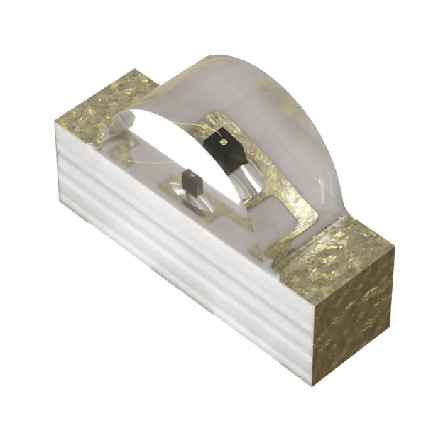
| 2H1204NX1TLA0001 | 1204 | Side | 3.2 × 1.0 × 1.5 | Clear | -40 to +85 | 1.2 | 1.5 | 940 | 120 |
| 2H0603NX1TRA0001 | 0603 | Top | 1.6 × 0.8 × 0.6 | Clear | -40 to +85 | 1.2 | 1.5 | 940 | 120 |
| 2H0805NX1TJA0001 | 0805 | Top | 2.0 × 1.25 × 0.85 | Clear | -40 to +85 | 1.2 | 1.5 | 940 | 120 |
| 2H1206NX1TTA00S1 | 1206 | Side | 3.2 × 1.6 × 2.65 | Clear | -40 to +85 | 1.2 | 1.5 | 940 | 20 |
| 2H1206NX1TMA0001 | 1206 | Top | 3.2 × 1.6 × 0.9 | Clear | -40 to +85 | 1.2 | 1.5 | 940 | 120 |
| 2H1206NX1TQA0001 | 1206 | Top | 3.2 × 1.6 × 1.85 | Clear | -40 to +85 | 1.2 | 1.5 | 940 | 20 |
| 2H1206NX1TQA00R1 | 1206 | Reverse Mount | 3.2 × 1.6 × 1.85 | Clear | -40 to +85 | 1.2 | 1.5 | 940 | 20 |
The matched receivers: phototransistors and photodiodes
Matched receivers in the same package sizes as the emitters are listed below.
Phototransistors:
The receiver wavelength range is 700 to 1100 nm, so a single silicon detector covers both 850 and 940 nm — one receiver part can pair with either emitter wavelength.
| Part Number | Pkg | View | Dimensions (mm) | Epoxy | Operating Temp (°C) | Wavelength Range (nm) | Receiving Angle (°) |
|---|---|---|---|---|---|---|---|
| 2H1204PT1HLA0001 | 1204 | Side | 3.2 × 1.0 × 1.5 | Black | -40 to +85 | 700–1100 | 120 |
| 2H0603PT1HRA0001 | 0603 | Top | 1.6 × 0.8 × 0.6 | Black | -40 to +85 | 700–1100 | 120 |
| 2H0805PT1HJA0001 | 0805 | Top | 2.0 × 1.25 × 0.85 | Black | -40 to +85 | 700–1100 | 120 |
| 2H1206PT1HMA0001 | 1206 | Top | 3.2 × 1.6 × 0.9 | Black | -40 to +85 | 700–1100 | 120 |
| 2H1206PT1HQA0001 | 1206 | Top | 3.2 × 1.6 × 2.65 | Black | -40 to +85 | 700–1100 | 40 |
| 2H1206PT1HQA00R1 | 1206 | Reverse Mount | 3.2 × 1.6 × 2.65 | Black | -40 to +85 | 700–1100 | 40 |
Photodiodes:
| Part Number | Pkg | View | Dimensions (mm) | Epoxy | Operating Temp (°C) | Wavelength Range (nm) | Receiving Angle (°) |
|---|---|---|---|---|---|---|---|
| 2H3227PD1HMA0101 | 3227 | Top | 3.2 × 2.7 × 0.9 | Black | -40 to +85 | 700–1000 | 130 |
| 2H5040PD1TKA0101 | 5040 | Top | 5.0 × 4.0 × 1.05 | Clear | -25 to +85 | 400–1100 | — |
Telcona's role
Edison Opto's CHIP IR LEDs are simple components in isolation, but the choices that surround them — wavelength, package, direction, viewing angle, and the matching receiver — determine whether a sensor works in dim shop light or fails under direct sun, holds millimetre alignment after a thousand pulses, and survives a decade in factory air.
Telcona, as Edison's authorised European distribution and engineering partner, takes the catalogue from Taipei and turns it into specified, sampled, and supported BOM lines for European sensor customers — with pricing aligned to volume, allocation priority backed by 40 years of supplier relationships, and engineering support from Telcona's Belgrade Technology Centre.
👉 For free samples of Edison's CHIP IR emitters and receivers, custom selection support, or a complete BOM analysis for your next optical sensor program, please contact Telcona, your trusted partner for high-performance electronic components.