You order 4,000 red LEDs of the same MPN, from the same manufacturer, of the same production reel. You expect them to be identical. The catch is — they are not.
This is not a defect. Each LED is built up through about a dozen manufacturing steps, and at every step, small imperfections sneak in. By the time the LED comes off the production line, all those small variations have been added together to produce a final part that is similar but not identical to its neighbours.
Where do the variations come from?
- Every LED begins life on a very precisely grown crystal disc called a wafer. But not all wafers are identical: some will have micro-cracks that are not visible to the human eye, or on some the polished surface might be slightly bumpy — the wafer is not the same thickness from edge to edge. These small differences will pass through to every LED made on that wafer.
- The actual light-producing layer of the LED is grown on top of this wafer atom by atom. Gases flow over the hot wafer and slowly deposit a thin crystalline film. But the temperature of the wafer is slightly different across its surface, or the gas mixture may create a layer of varying thickness by essentially shifting a few atoms across the wafer. Because the colour of light an LED emits is determined by the exact recipe of this layer, even a tiny variation in the mix shifts the colour by a few nanometres.
- Cutting up the wafer is another cause for concern. Once the layer is grown, one wafer contains thousands of individual LED chips packed onto its surface. The wafer is then cut into separate chips with a laser. Cutting introduces tiny chips and scratches at the edges of each die.
These deviations can be considered small — a few millivolts of voltage, a few nanometres of wavelength, a few percent of light output — but they are real, and they are big enough to spoil a video wall and make it look like a patchwork quilt.
The way the industry handles this is called binning.
The factory cannot make every LED the same, so it measures each one, labels it and sorts it into a designated bin.
The process is transparent so that each ordered batch has clearly stated bin codes. Below is an example of a product label, including bin codes.
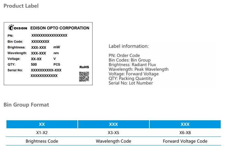
Excerpt from the Federal 3535 Gen2 2W IR660 datasheet focusing on the label, MPN: 2FX002EX00130001.
So, let's learn to read the bins. Understanding binning is one of those small details that separates a smooth LED project from a frustrating one.
What is LED binning?
Binning is the practice of measuring every finished LED at the end of the production line and then sorting the parts into labelled groups, called bins, according to the values measured. Each bin covers a narrow range of one or more parameters.
The bin labels are printed on the reel and on the outer carton, and they are stated in the LED's datasheet.
Different types of LEDs will have different parameters that should be binned — it is not the same if you are ordering an IR LED or a simple coloured LED.
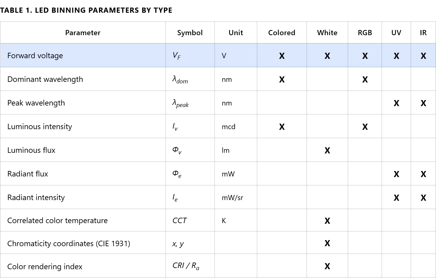
Let's discuss LED bins
1. Forward voltage bins
This bin applies to every LED type.
The forward voltage is the voltage drop across the LED at its rated forward current.
Parts are sorted into forward voltage windows that are typically 0.15 V wide, depending on the LED type. Bin codes such as B05, B20, or B35 indicate the starting voltage of each window.
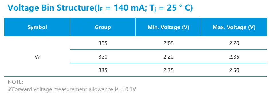
Excerpt from the PLCC 3528 datasheet focusing on voltage bin structure. B05, B20 and B35 are bins each defining a specific forward voltage range, MPN: 2T03X5RX00031SAA.
In one batch the biggest quantity of produced LEDs will match the typical value of forward voltage, with smaller quantities falling into the lower and upper bins.
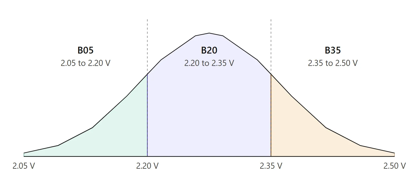
Voltage distribution across the voltage range. Most LEDs will fall into the B20 bin and the values will be close to the typical value stated in the datasheet.
Voltage binning matters because the LED is a diode, and the current-voltage curve is exponential. A few hundred millivolts of horizontal shift produces an order of magnitude difference in current at the same applied voltage.
2. Dominant wavelength bins
This bin applies to coloured LEDs and to each channel of RGB packages.
The factory measures the perceived colour of each LED on the CIE 1931 chromaticity diagram.
Parts are sorted into dominant wavelength windows that are typically 4 to 5 nm wide. Bin codes such as R16 or R20 indicate the starting wavelength in nanometres.
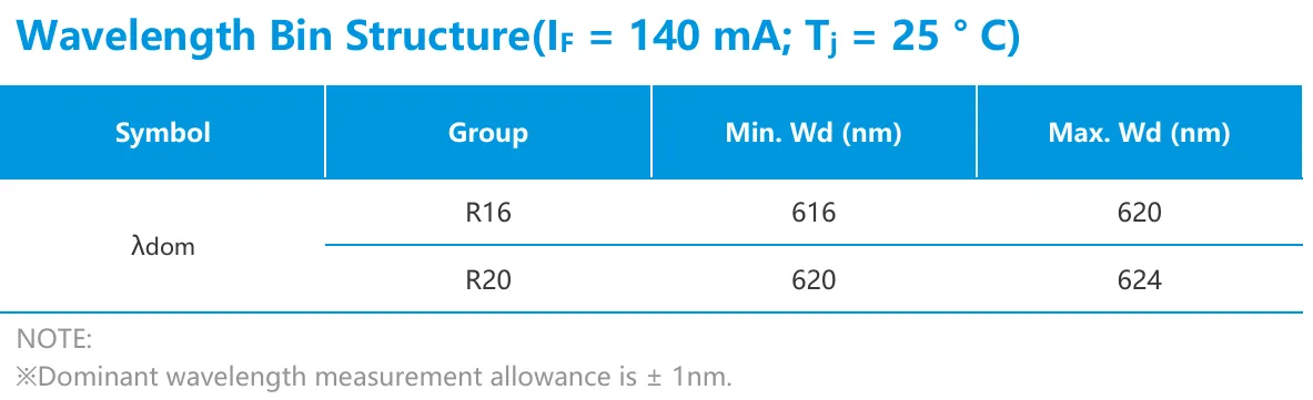
Excerpt from the PLCC 3528 datasheet focusing on dominant wavelength bin structure. Two bins are stated, R16 and R20, MPN: 2T03X5RX00031SAA.
The consequence is purely visual. Two LEDs from neighbouring bins look slightly different to the human eye when placed side by side.
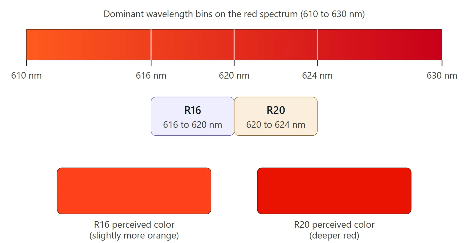
Illustration of colour change depending on the wavelength bin.
3. Peak wavelength bins
This bin replaces dominant wavelength for UV and IR LEDs. These devices emit outside the visible spectrum, so the perceptual colour concept does not apply.
The factory uses a spectrometer to measure the wavelength at which the LED reaches peak intensity. Parts are sorted into peak wavelength windows that are typically 5 to 10 nm wide.
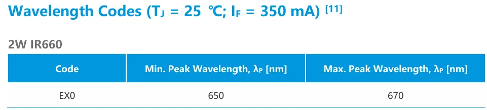
Excerpt from the Federal 3535 Lens IR Series datasheet focusing on peak wavelength bin structure, MPN: 2FX002EX00130001.
The consequence depends on the application. UV curing chemistry only reacts at certain wavelengths. IR sensors only respond to certain wavelengths. A 20 nm shift can drop curing efficiency or push the LED outside the detector's sensitive band entirely.
4. Luminous intensity bins
This bin applies to coloured LEDs and to each channel of RGB packages.
The factory measures how much visible light each LED emits in its forward direction. The unit is millicandela (mcd).
Parts are sorted into luminous intensity windows where the brightest LED in a bin emits roughly 25 to 30 percent more light than the dimmest. Bin codes are usually letters such as DB, EA, or EB, with each step a brighter range.
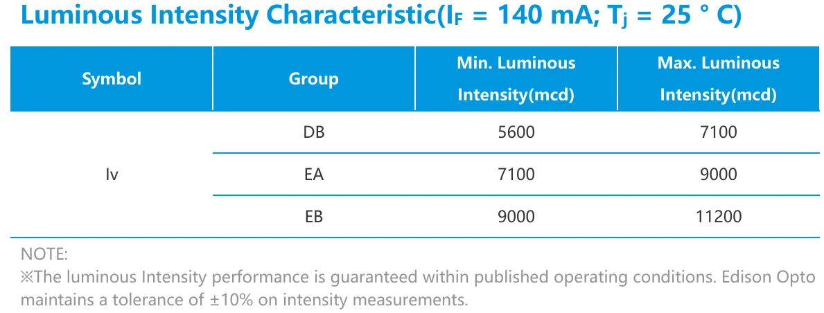
Excerpt from the PLCC 3528 datasheet focusing on luminous intensity bin structure, MPN: 2T03X5RX00031SAA.
The consequence is brightness uniformity. A single LED with a mixed bin label looks fine on its own. A row of indicator LEDs from mixed bins shows a visible difference in brightness.
5. Luminous flux
This bin applies to white LEDs used for general lighting.
Instead of measuring light in one direction, the factory measures the total light emitted in all directions using an integrating sphere. The unit is lumen (lm).
Parts are sorted into luminous flux windows that are typically 10 to 15 percent wide.
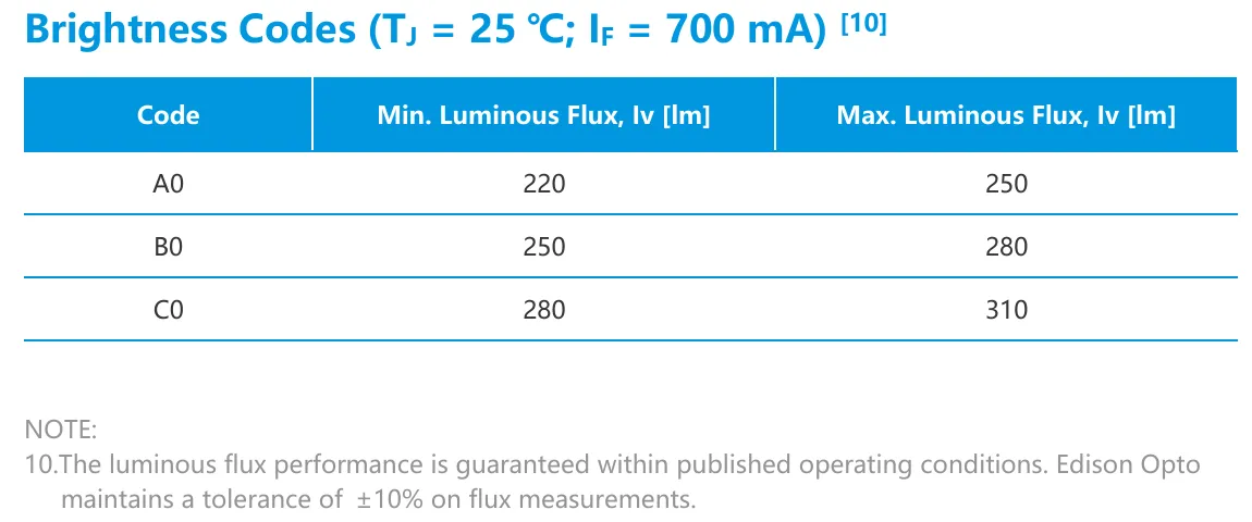
Excerpt from the CA2016T 2W Cool White datasheet focusing on luminous flux bin structure, MPN: 2DF102CW81F11011.
The consequence shows up in lighting design. Two LEDs from neighbouring flux bins produce noticeably different brightness when installed side by side in the same luminaire.
6. Radiant flux
This bin replaces luminous flux for UV and IR LEDs.
Photometric units such as lumens assume the human eye is looking at the light. UV and IR are invisible to humans, so the factory measures raw optical power instead. The unit is milliwatt (mW).
Parts are sorted into radiant flux windows that are typically 10 to 20 percent wide.
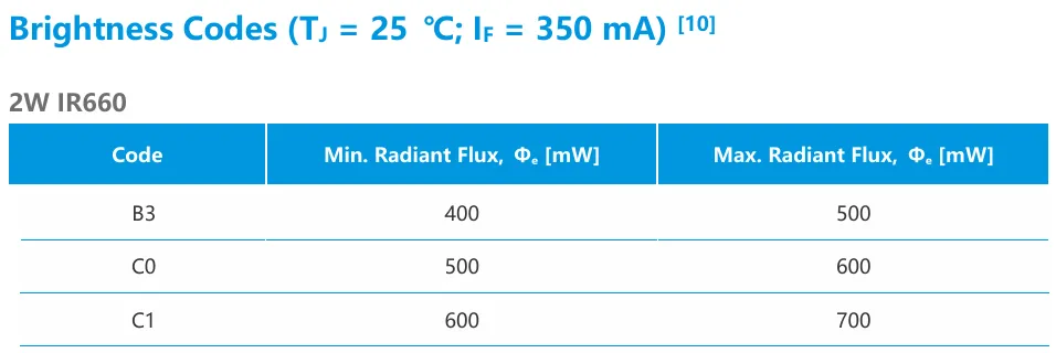
Excerpt from the Federal 3535 Lens IR Series datasheet focusing on radiant flux bin structure, MPN: 2FX002EX00130001.
The consequence is application specific. In UV curing, more milliwatts means faster cure times. In IR sensing, more milliwatts means longer detection range.
7. Radiant intensity
This bin applies to directional UV and IR LEDs, where the emitted light is concentrated into a narrow beam by a built-in lens.
The factory measures optical power per unit of solid angle. The unit is milliwatt per steradian (mW/sr).
Parts are sorted into radiant intensity windows that are typically 15 to 25 percent wide. The consequence is the same as for radiant flux, but it matters for narrow-beam applications such as IR remote controls, time-of-flight sensors, and UV spot-curing tools. A higher bin LED reaches further or cures faster in its targeted spot.
8. Correlated colour temperature (CCT)
This bin applies to white LEDs.
The factory measures the apparent warmth of the white light produced by each LED. The unit is Kelvin (K). A 2700 K LED looks warm and yellowish, like a classic incandescent bulb. A 6500 K LED looks cool and bluish, like midday daylight. Parts are sorted into CCT windows that are typically 100 to 300 K wide. The ANSI C78.377 standard defines bins around the most common nominal temperatures: 2700 K, 3000 K, 3500 K, 4000 K, 5000 K, and 6500 K.
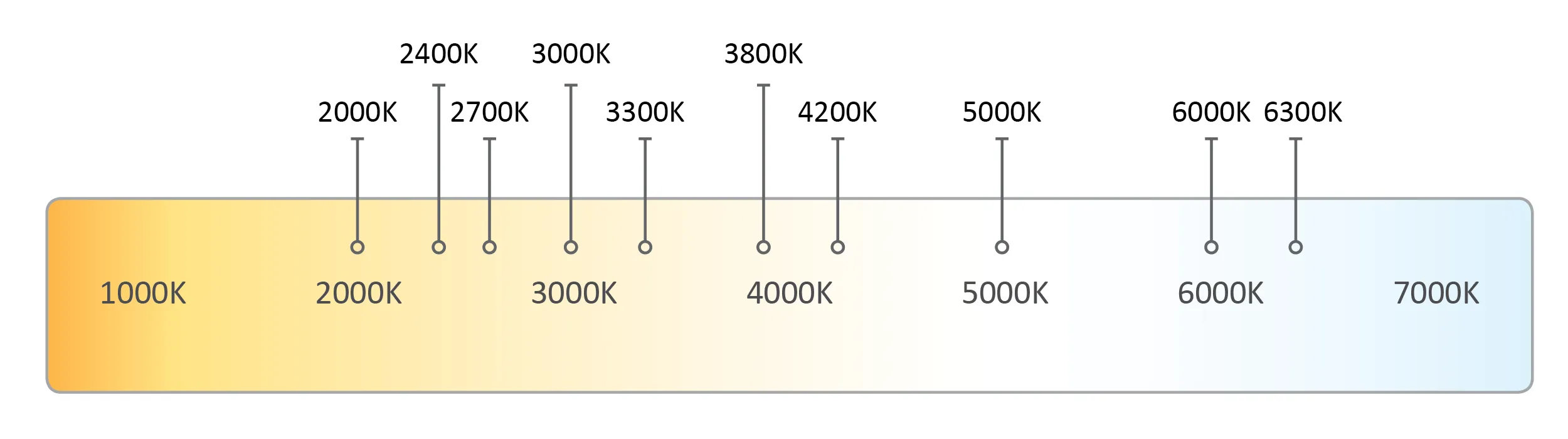
Illustration of CCT scale.
The consequence is direct visual appearance. Two LEDs from neighbouring CCT bins, installed in adjacent fixtures, look noticeably different in tone.
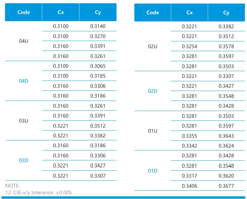
9. Chromaticity coordinates (x, y)
This bin is the finer companion to CCT, also for white LEDs.
While CCT collapses the white shade into a single number, chromaticity tracks the exact colour point on the CIE 1931 diagram using two coordinates, x and y. The factory groups LEDs into MacAdam ellipses, small regions of the diagram inside which the human eye cannot tell two colours apart.
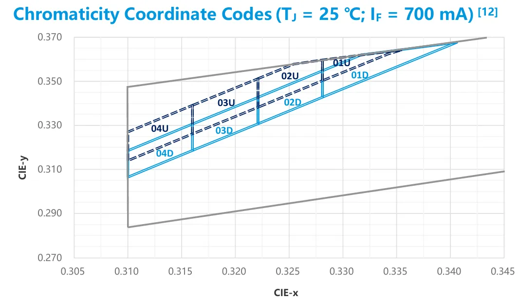
A 3-step ellipse is very tight and is suitable for premium architectural lighting where uniformity must be invisible. A 7-step ellipse is loose and allows visible tint differences between adjacent LEDs.
The consequence is colour matching precision. Two LEDs with the same CCT can still look different if they sit on opposite sides of a wide MacAdam ellipse, so high-end projects specify both CCT and MacAdam step.
10. Colour rendering index
This bin applies to white LEDs used for general lighting.
The number describes how accurately the LED reveals the natural colour of objects, compared to a reference light source such as daylight.
The scale runs from 0 to 100. Higher is better. Parts are sorted into broad ranges such as CRI 80 and above, CRI 90 and above, and CRI 95 and above.
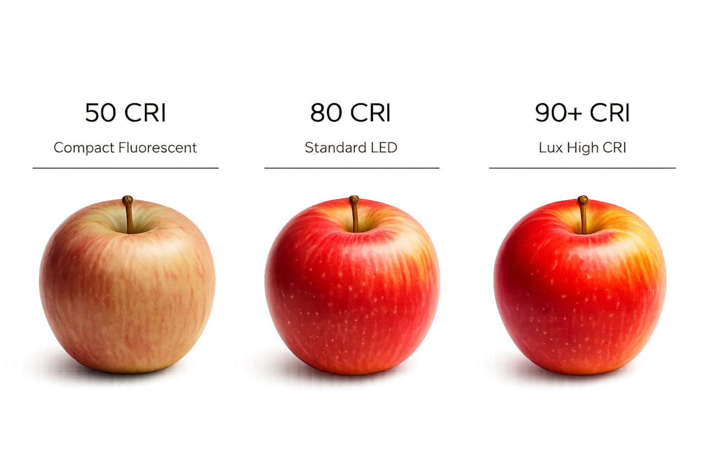
Illustration of CRI scale.
The consequence is aesthetic but matters in specific contexts. A CRI 70 LED makes meat in a butcher's shop look grey. A CRI 90 LED makes the same meat look fresh and red. Galleries, hospitals, retail spaces, and any environment where colour appearance matters specify high-CRI bins, which cost more because they require multiple phosphor types in the coating.
How to handle binning in your own design and procurement
A few patterns that work in practice:
- For non-critical work where uniformity does not matter (hidden indicator LEDs, engineering prototypes, single-LED status lights), specify the full datasheet range and accept whatever the factory ships. This is the cheapest path and the right one for many use cases.
- For visually uniform work, specify a single intensity bin and a single wavelength bin on your BOM line. Expect a price premium of 10 to 30% and possible lead-time extension, because the factory has to set aside parts that meet your criteria.
- For early-stage design validation, deliberately test with parts from the extremes of the bin distribution. Order small quantities from the lowest and highest bins and verify that your circuit, your thermal design, and your visual appearance hold up with both.
What Telcona offers
Specifying bins in a BOM is one thing. Knowing which bins are in stock, which require pre-ordering from the factory, and which are produced often enough to be worth specifying in volume is another.
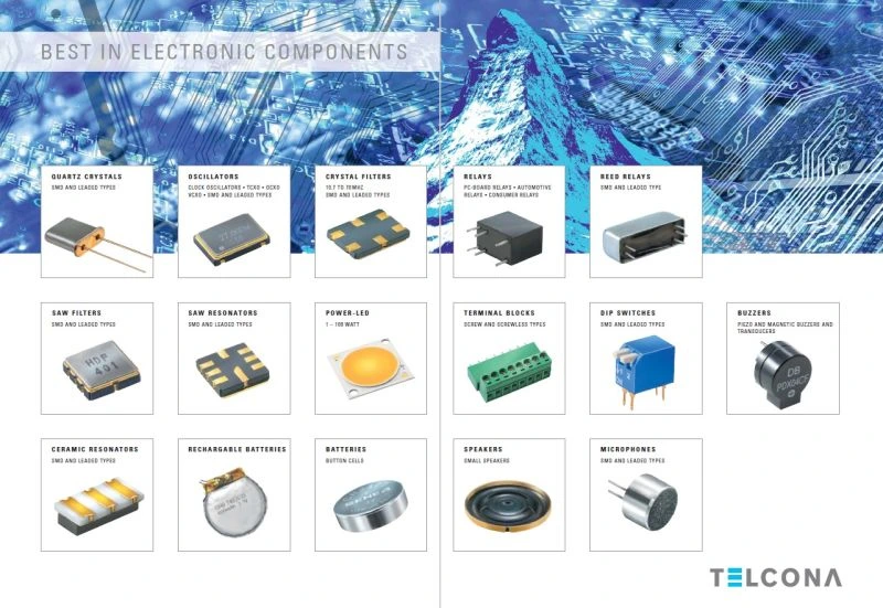
At Telcona, we have spent 40 years building direct relationships with manufacturers across Japan, China, Taiwan, and Hong Kong. For LEDs, our authorised partner is Edison Opto, the Taiwan-listed LED specialist.
If you are starting a new LED design, or troubleshooting visual uniformity issues on an existing one, talk to us before you place the order. Bin specifications are much easier to get right at the start than to fix after a production run.