Contact Sales Team

Insulin pumps and Continuous Glucose Monitoring (CGM) devices market
Diabetes is one of the largest and fastest-growing chronic disease burdens in the world. The International Diabetes Federation estimates that 589 million adults were living with diabetes in 2024. This number is predicted to reach roughly 853 million by 2050.
Around 9.1 million people live with type 1 diabetes, the population most dependent on insulin-delivery and glucose-monitoring hardware.
Two device classes make up modern diabetes management:
- Insulin pumps and
- Continuous glucose monitors (CGM)
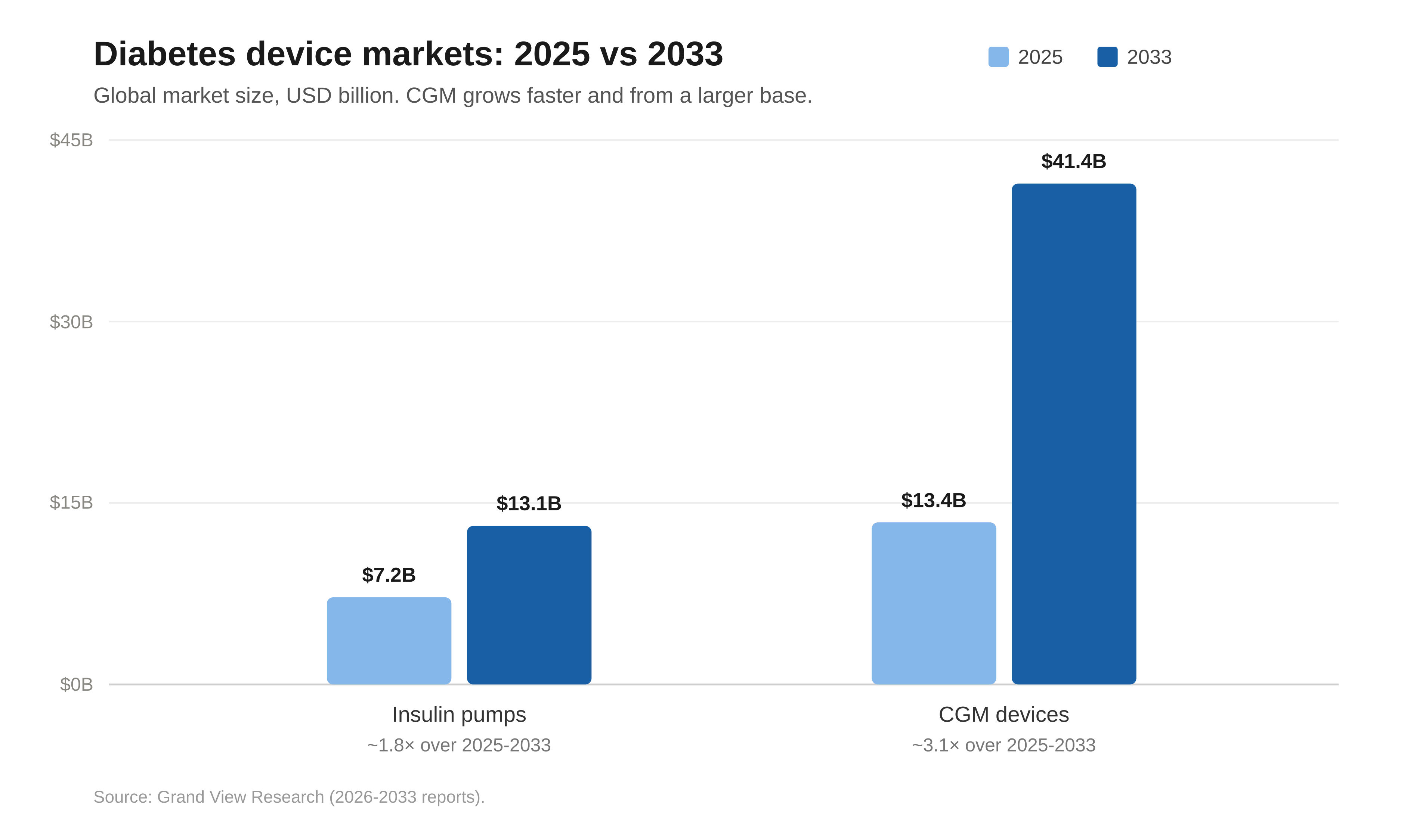
Grand View Research estimates the global insulin pump market at USD 7.2 billion in 2025, growing to USD 13.1 billion by 2033. The CGM segment is larger and faster: Grand View Research puts the CGM devices market at USD 13.4 billion in 2025, reaching USD 41.4 billion by 2033.
Like everything today, these devices are being pushed in the same direction; make them smaller, with lower-power, with more reliable building blocks, including the frequency-control parts that keep these devices on time.
How insulin pump works
There are two popular architectures of insulin pumps, tethered insulin pumps and tubeless patch systems, that have similar electronics but are packaged differently, which affects component choice. A tethered pump keeps the motor, battery, and refillable reservoir in a reusable body that connects through a thin tube to a separate disposable infusion set on the skin, whereas a tubeless (patch) pump integrates all of that into one small disposable worn directly on the body and controlled wirelessly, with no tubing.
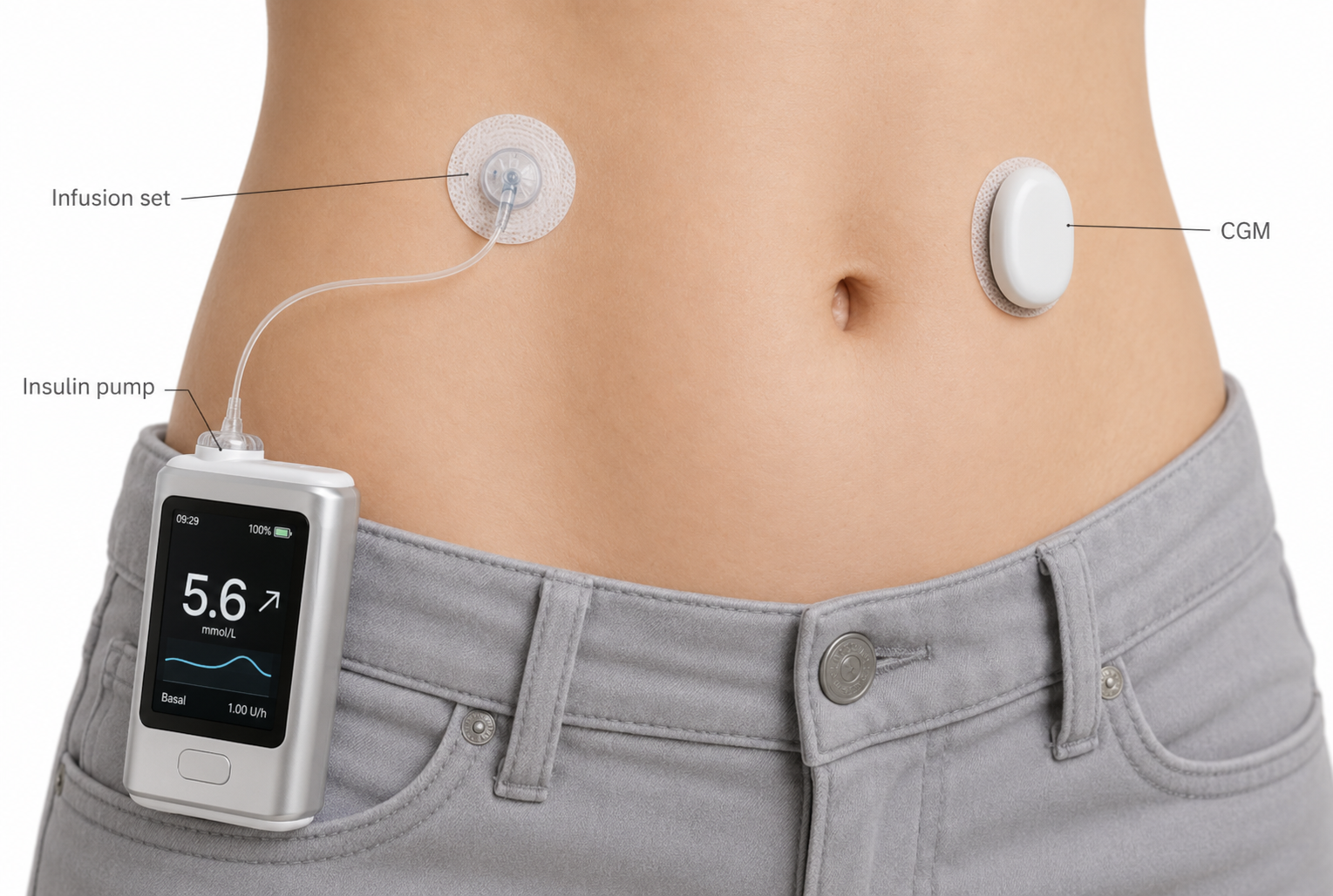
Illustration of insulin pump and CGM device in AID system
Mechanically, an insulin pump is a precision metering pump. A small electric motor turns a lead screw that drives a plunger through the insulin reservoir, and the firmware converts each dose, expressed in insulin units, into a counted number of motor micro-steps.
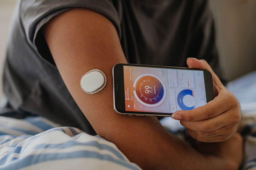
In an automated insulin delivery (AID) system the pump does not work alone: it is paired with a continuous glucose monitoring (CGM) device. The CGM measures glucose and sends each reading over a radio link, usually Bluetooth Low Energy (BLE), to the pump, where the system's control algorithm decides how much insulin to deliver and triggers the motor.
Underneath, the pump and the CGM are built on the same kind of platform. Both are battery-powered, drawing from AAA or coin cells or a rechargeable LiPo, both run their control firmware on a low-power microcontroller (MCU), and both keep absolute time with a real-time clock (RTC).
A patch pump works on the same metering principle, just repackaged. Instead of a reusable body feeding a tube, the motor, drive mechanism, insulin reservoir, cannula, battery, MCU, and radio are all integrated into one small pod worn directly on the skin. When the pod is applied it inserts its own cannula, then meters insulin exactly as a tethered pump does, a motor advancing a plunger in counted micro-steps. There is no handset wired to the pump: the user controls it wirelessly, over the same BLE link, from a phone app or a dedicated controller, and the whole pod is discarded and replaced every few days.
Frequency control components in insulin pumps
Every function described so far depends on the device knowing what time it is. Insulin is dosed on a schedule, glucose is sampled at fixed intervals, and the radio link only works if both ends agree on timing. That sense of time does not come from the microcontroller or the radio on their own; it comes from a quartz crystal, the small frequency reference that gives every clock in the system its beat.
Frequency-control components sit in two places, and the distinction matters for sourcing.
- The RTC reference is a 32.768 kHz tuning-fork crystal: the heartbeat for timekeeping that timestamps every glucose reading, schedules insulin delivery, and maintains the dosing calendar.
- The MCU and radio reference is a higher-frequency part, typically an MHz-range AT-cut crystal or, where tighter stability is needed, a TCXO, that clocks the MCU core and the radio.
Both references matter, but they pull on different requirements.
The MHz MCU and radio reference is largely set by the processor and the Bluetooth link and is best chosen alongside them.
The 32.768 kHz RTC crystal, by contrast, is where timekeeping, dosing accuracy, battery life, and package size meet in a single part, and it is the one most often left to the end of a design.
The rest of this article focuses there: the requirements that a wearable insulin pump place on its RTC crystal, and the Citizen parts that meet them.
Design requirements of the RTC reference crystal
The RTC uses one frequency, 32.768 kHz, but a handful of crystal parameters decide whether it keeps accurate time, at low power, on the body. These are the requirements the application imposes before any specific part is chosen.
Nominal frequency. 32.768 kHz on every part. It is 2 to the 15th power, so a 15-stage divider gives an exact 1 Hz tick. That is why it is the universal RTC frequency.
Tolerance at 25 °C. The initial room-temperature accuracy, quoted in ppm. It is a fixed offset that accumulates over time, so tighter grades buy better timestamp precision at higher cost.
Frequency stability. A tuning-fork crystal is most accurate at its turnover temperature, near 25 °C, and drifts away along a parabola set by its temperature coefficient β (around −0.034 ppm/°C²). The square term dominates: at 37 °C body heat the shift is only about −4.9 ppm, but at the cold end of a −40 °C rating it reaches roughly −144 ppm (calculated from β). Temperature, not room-temperature tolerance, is the dominant error source, so predictable parabolic behavior matters more than a single headline ppm figure.
Operating and storage temperature. The application sees skin temperature in use, but shipping, warehousing, and reflow reach far wider. The rating defines what part survives, not only where it runs.
Drive level. The power the oscillator feeds into the crystal. Lower drive means less continuous current, and since the RTC oscillator never sleeps, that current is always on; staying under the rated maximum also protects the crystal from accelerated aging.
ESR (R1). How hard the crystal is to start and keep oscillating. Lower ESR gives more start-up margin and lets the oscillator run at lower current, which matters most on a coin cell.
Package and qualification. Footprint and height decide what fits. Standard parts are common, but patch pumps and on-body sensors push toward progressively smaller outlines.
Aging. The slow, permanent drift of frequency over time; the highest in the first year.
How can Telcona support you
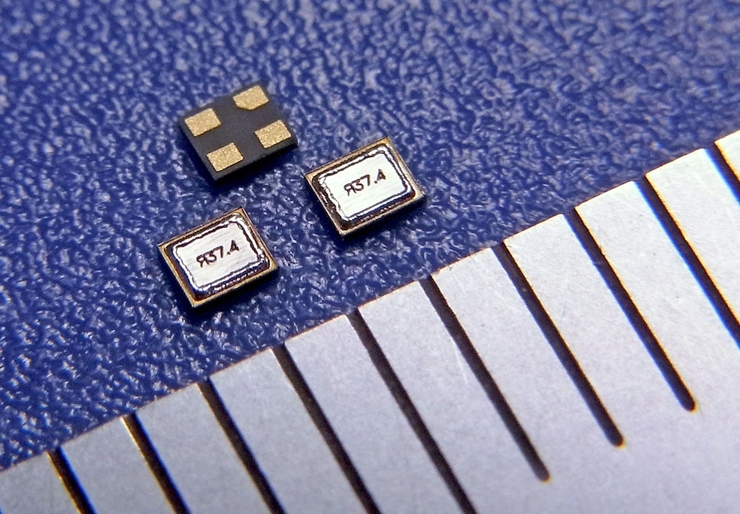
Citizen Finedevice, part of the Citizen Watch group (Citizen is a registered trademark of Citizen Watch Co., Japan), has built 32.768 kHz tuning-fork crystals over half a century. The same timekeeping heritage that runs quartz watches is what a diabetes device needs for its RTC.
The following parts are proposed for RTC timekeeping.
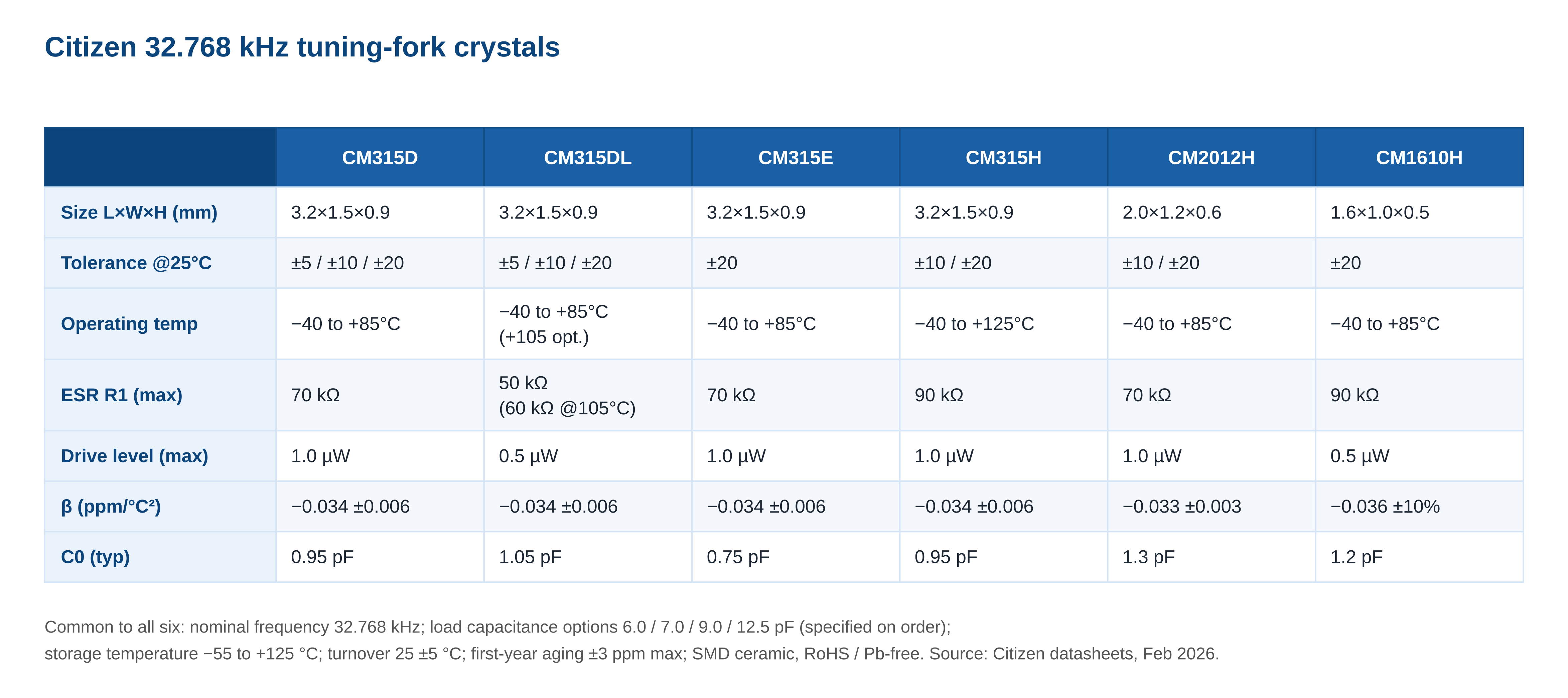
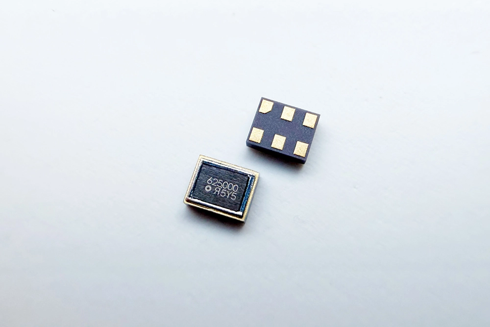
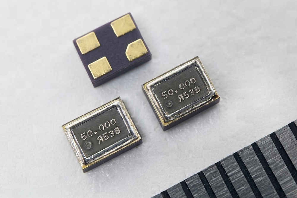
- CM315D is the mainstream 32.768 kHz RTC reference in a 3215 package.
- CM315DL keeps the same footprint of 3215 but halves drive level from 1.0 µW to 0.5 µW, and drops ESR to 50 kΩ, the choice for coin-cell and patch-pump power budgets.
- CM315E adds a metal lid for EMI containment near a 2.4 GHz radio.
- CM315H is AEC-Q200 qualified to +125 °C and listed for industrial and medical non-life-dependent use.
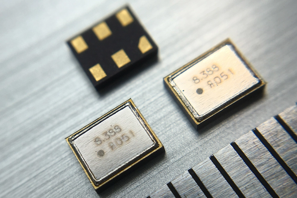
- CM2012H and CM1610H carry the same electrical behavior into smaller footprints, 2012 and 1610, for tubeless patch and on-body sensor designs where area and height are the binding constraint.
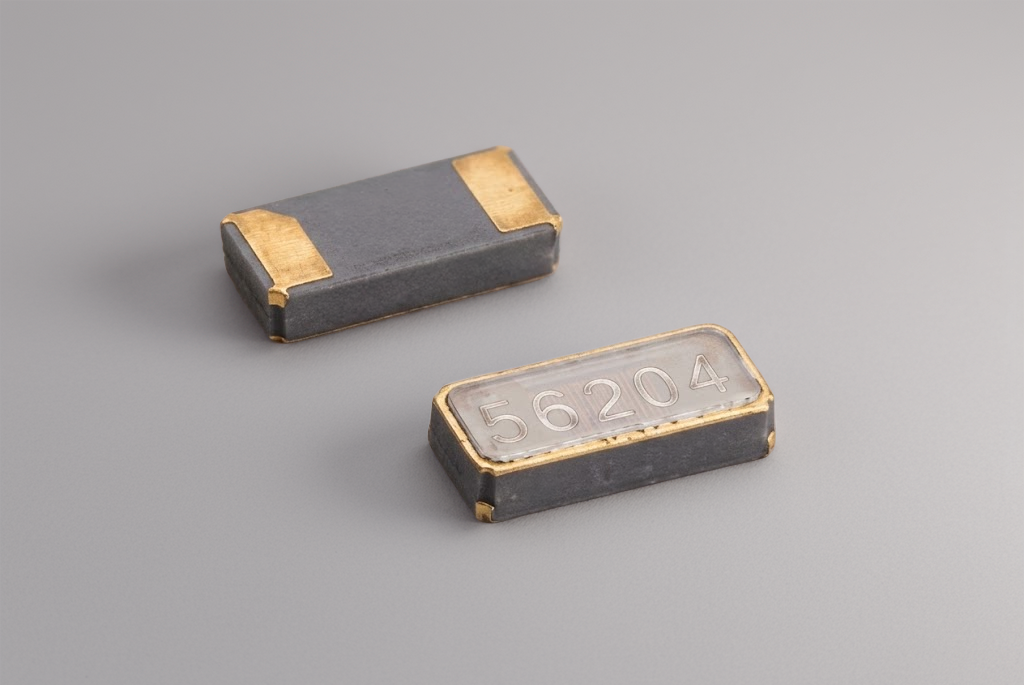
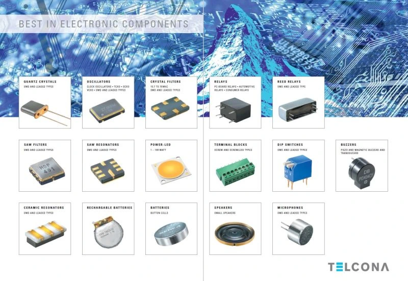
Telcona AG is the authorized European supply and components engineering partner for Citizen Finedevice. On a diabetes-device program, Telcona's role is practical.
- Samples are available on request.
- A crystal matching test is available to confirm load capacitance and negative-resistance margin against the actual PCB and MCU oscillator, which is the single most common cause of a crystal that runs in prototype but stalls in production.
- The Belgrade Technology Center at Telcona supports engineering questions directly.
- Just-in-time logistics and buffer stock protect the production line.
- BOM-level support through Telcona's Luminovo-integrated workflow covers quoting, cross-referencing, and obsolescence checks.
For a medical OEM, that combination of Swiss accountability, named-manufacturer transparency, and local engineering shortens the path from datasheet to a qualified, supplied part. To request samples or a matching test, contact info@telcona.com.